|
|
 |
|
|
|
|
|
|
|
 |
|
●
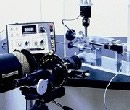
光彈測試儀與光彈材料
●
Photo Stress ●
|
|
|
|
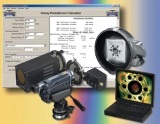 |
產品特色:
Easy to learn and use
Instantly determine
directions of principal stresses on the structure
Instantly calculate
strain and stresses at any selected point
Locate
Assembly Stresses (總應力分析),
Residual Stresses (殘留應力
分析),
Yielding (楊氏係數)
, and verify
FEA
Transmit PhotoStress®
patterns and test data via computer networks and the Internet
Fast, cost-effective
method of improving structural design in aerospace, automotive, military,
civil engineering, industrial applications |
|
|
|
|
|
|
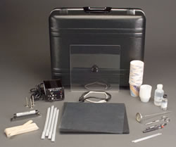
【產品圖】 |
 |
 |
|
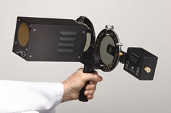
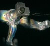
Hand-held portable operation |
LF/Z
reflection polariscope system |
|
(手持式操作) |
(反射式光彈儀) |
 |
 |
|
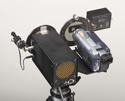
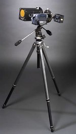
Tripod
mounted |
Coating
application kit |
|
(三腳架) |
(耗材組) |
|
|
|
【應用實例A】 |
|
Diesel Engine
Flywheel Case History
【柴油引擎飛輪分析案例】 |
 |
 |
 |
|
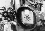
Photo A |
Photo B |
Photo C |
|
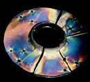
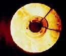
A
diesel engine flywheel was failing around the bolt circle.
Photo A shows a flywheel coated with PhotoStress plastic,
and then bolted to the diesel engine for dynamic testing.
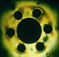
When the bolts were tightened, very high stresses appeared,
which were well above the design limit of the material as
shown in Photo B. Superposition of forces due to dynamic
testing caused premature fatigue failure. The major problem
was thus defined by PhotoStress analysis as one of
assembly-induced stresses. Redesign of the flywheel (where
it mated to the shaft of the diesel engine) significantly
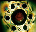
reduced the initial assembly stresses as shown in Photo C. |
|
【應用實例B】 |
|
Metal Fan Hub Case
History 【金屬風扇分析案例】 |
 |
 |
|
Photo A |
Photo B |
|
A
metal fan hub was failing in service where the hub shaft
support was welded to the flange. Analytical studies
predicted low stress levels during the dynamic loading
sequence. Strain gage measurements near the weldment
supported this prediction. Several of the fan hubs were
fabricated for test purposes, and PhotoStress coatings were
contoured and bonded over the surface area. After
application of the coating, the hubs were sawed through,
releasing the internal forces (residual stresses) developed
by nonuniform heating during the welding process. The fringe
patterns in the PhotoStress coating shown in Photo A
revealed locked-in residual stresses, which were of very
high magnitude in the welded area. The modest cyclic
stresses, superimposed upon the high residual mean stresses,
were sufficient to produce field failures. Subsequent test
samples were stress-relieved after fabrication, and
PhotoStress analysis of the stress-relieved hub showed no
evidence of residual stress after cutting, as shown in Photo
B. |
|
【應用實例C】 |
|
Element Analysis -
Steering Knuckle Case History
【方向元件分析案例】 |
 |
 |
 |
 |
|
Photo A |
Photo B |
Photo C |
Photo D |
|
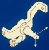
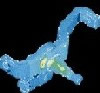
PhotoStress® is a complimentary technique to FEA for
achieving optimal and verifiable stress analysis of a
design. In this example, an FEA analysis of an automotive
steering knuckle was conducted, and after manufacturing the
actual part, PhotoStress® testing was chosen to verify the
FEA results. Photo A shows an illustration of the steering
knuckle and how the directional loads were applied. Photo B
shows the FEA results indicating that the highest stresses
are located in the fillet area of the protruding spindle.
Photo C shows a physical model of the actual part in the
test rig for PhotoStress® testing. Photo D shows the results
of PhotoStress® analysis confirming the general location of
the significant stresses revealed on the FEA model.
PhotoStress® measurement, however, showed that the peak
stress magnitudes were approximately 20 percent higher than
the computer solution.
|
|
|
|
|
|
|
|